Getting your Tesla Wall Connector installed at home starts with understanding exactly how it needs to be wired. A proper tesla wall connector wiring diagram shows you the terminal connections, wire routing, and grounding requirements that make the difference between a safe, code-compliant installation and a potential fire hazard. Whether you’re a homeowner trying to understand the scope of the project or an electrician looking for quick reference specs, this guide breaks it all down.
We install EV charging stations across the Greater Phoenix Metro Area every week at AZ DC Electric, and the Tesla Wall Connector is by far the most common unit we work with. That hands-on experience has taught us exactly where people get tripped up, undersized wire gauges, mismatched breaker ratings, and incorrect terminal connections top the list. These aren’t small mistakes. They can damage your charger, trip your panel, or create serious safety risks.
This guide covers the complete wiring diagram for the Tesla Wall Connector, including L1, L2, and ground terminal connections, recommended wire sizes for different circuit lengths, and the correct breaker specifications. By the end, you’ll have a clear picture of what this installation involves and what it takes to do it right.
What you must know before you start
Before you pull a single wire, you need to understand the electrical requirements and code rules that govern this installation. The Tesla Wall Connector runs on a 240-volt, two-pole circuit, which means it draws power from both hot legs of your panel. That’s a different animal from a standard 120-volt outlet, and every decision you make about breaker size, wire gauge, and conduit runs from that core fact. Skipping this groundwork is how homeowners end up with a charger that trips the breaker every time they plug in.
Tesla Wall Connector generations and their specs
Tesla has released multiple generations of the Wall Connector, and each generation has different internal wiring and terminal layouts. The current model is the Gen 3 Wall Connector, which supports up to 48 amps of continuous charge current on a 60-amp circuit. The older Gen 2 unit maxed out at 40 amps on a 50-amp circuit. Before you reference any tesla wall connector wiring diagram, confirm which generation you have, because the terminal block location, wire entry points, and DIP switch configuration differ between models. You can find your unit’s generation printed on the label inside the charging cable compartment door.
| Generation | Max Charge Current | Required Breaker | Wire Entry |
|---|---|---|---|
| Gen 2 | 40A continuous | 50A two-pole | Bottom |
| Gen 3 | 48A continuous | 60A two-pole | Bottom or conduit knockout |
NEC code requirements you must follow
The National Electrical Code (NEC) governs EV charger installations across the United States, and most local jurisdictions in Arizona adopt it with minimal amendments. Article 625 of the NEC covers EV charging equipment specifically. One of the most critical rules in that article is the 125 percent continuous load rule: because an EV charger runs at full load for extended periods, your circuit must be rated for 125 percent of the charger’s continuous current draw. That’s why a 48-amp charger needs a 60-amp breaker and not a 50-amp one (48 x 1.25 = 60).
The 125 percent continuous load rule is the single most misunderstood requirement in EV charger installations. Getting this wrong means your breaker may not be code-compliant, even if it appears to work fine day-to-day.
Your jurisdiction almost certainly requires a permit for this installation, including Scottsdale, Mesa, Chandler, and every other city in the Greater Phoenix Metro Area. That permit triggers an inspection, which means a licensed inspector will review your wiring, conduit work, and breaker connections before the job is considered complete. Pulling the permit before work starts protects you legally and keeps your homeowner’s insurance valid if an electrical issue ever occurs.
What to have ready before you start
Confirming your panel capacity upfront and gathering all materials before you begin saves you from stopping mid-job with an open panel. Check these items first:
- Panel capacity: Verify your main panel has an open two-pole slot and enough headroom to add a 60-amp breaker without exceeding the panel’s total amperage rating.
- Wire gauge: Have the correct gauge on hand based on your run length (covered in Step 3).
- Conduit: EMT or PVC conduit is required for any exposed runs in most jurisdictions.
- Permit: Apply before work starts, not after.
- Torque screwdriver: Tesla specifies torque values for terminal connections, and under-torqued connections cause heat buildup and arcing over time.
Having all of this confirmed before you open the panel keeps the job moving and keeps every connection safe and code-compliant from the first step to the last.
Step 1. Confirm power and Wall Connector model
Before you run any wire or mount the unit, you need two confirmed facts: what your electrical panel can actually support and which generation of Wall Connector you have. Starting without both pieces of information leads to buying the wrong materials or wiring a unit to specs that don’t match your specific model. This step takes less than 15 minutes and saves you from a costly redo.
Verify your panel has available capacity
Open your main panel door and look for an open two-pole slot large enough for a 60-amp breaker. Two-pole breakers take up two adjacent spaces in the panel, so you need two open slots side by side. If your panel has no open slots, you may be able to use a tandem breaker in some positions, but that depends on your panel’s brand and load center model. Check the inside of your panel door for a directory listing approved tandem positions before you assume a tandem will work.
If your panel is already at or near its rated capacity, adding a 60-amp circuit can push total load beyond safe limits. Have a licensed electrician evaluate your panel before you go any further.
Beyond open slots, confirm your panel’s total amperage rating covers the addition. A 200-amp panel serving a fully loaded home may not have the headroom for a 60-amp EV circuit without a proper load calculation. Write down your panel’s make, model number, and total rating before moving to the next step.
Identify your Wall Connector generation
Locate the label inside the charging cable compartment door on the front of your unit. The label shows the model number and generation. Gen 3 units carry model numbers starting with 1529788, while Gen 2 units carry older formats. This matters because any tesla wall connector wiring diagram you reference needs to match your specific generation. Terminal block locations, conduit knockouts, and DIP switch positions differ between the two, and using the wrong diagram causes direct miswiring at the terminal block.
Once you confirm the generation, note the maximum continuous amperage listed on the same label. That number drives every decision in Steps 2 and 3, from breaker size to wire gauge. Write it down next to your panel specs so you have both numbers in one place before you move forward.
Step 2. Choose breaker size and set charge rate
Once you know your panel has room and your Wall Connector generation is confirmed, breaker selection is your next decision. The breaker you install controls the maximum current the circuit can carry continuously, and it directly determines the charge rate you can configure on the unit itself. These two choices connect to each other, so you need to make both decisions at the same time rather than treating them as separate tasks.
Select the right breaker for your circuit
The NEC 125 percent continuous load rule sets the minimum breaker rating, but your breaker also needs to match what your panel manufacturer approves. Most 200-amp residential panels in Arizona accept a 60-amp two-pole breaker without issue, but you must use a breaker from the same manufacturer as your load center to maintain code compliance. Square D QO and Homeline panels require Square D breakers; Eaton BR and CH panels require their own line. Mixing brands voids the UL listing and will fail inspection.
Using an off-brand breaker in a name-brand panel is a code violation in most jurisdictions, even when it physically fits the slot.
Check with your local permit reviewer on whether your jurisdiction requires GFCI or AFCI protection on the EV circuit. Several cities in the Greater Phoenix Metro Area have adopted amendments requiring one or both on branch circuits of this type. Buying the wrong breaker style after the fact means an unnecessary return trip to the supply house.
Set the charge rate using the DIP switches
The Gen 3 Wall Connector uses an internal DIP switch bank on the circuit board to cap the maximum output current. Setting these switches correctly is a step that every tesla wall connector wiring diagram should highlight, because the switches must match the breaker you installed before you land a single wire. Tesla prints a DIP switch reference table inside the unit’s cover, but the table below covers the most common residential configurations you will encounter:
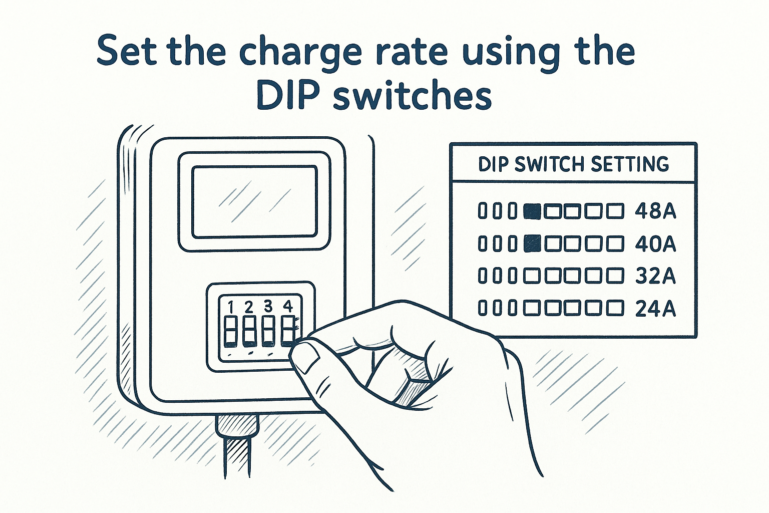
| DIP Switch Setting | Max Charge Current | Minimum Breaker Required |
|---|---|---|
| 48A (default) | 48A continuous | 60A two-pole |
| 40A | 40A continuous | 50A two-pole |
| 32A | 32A continuous | 40A two-pole |
| 24A | 24A continuous | 30A two-pole |
Adjust the DIP switches before you mount the unit to the wall, because the circuit board sits at the back of the enclosure and becomes much harder to reach once the unit is secured. If you installed a 60-amp breaker, leave the switches at the factory 48-amp default. If your panel only supported a 50-amp breaker, move the switches to the 40-amp position so your charge current and circuit rating stay aligned from the start.
Step 3. Size the wire and conduit
Wire sizing is where many installations go wrong. The wire gauge you choose must handle the full circuit amperage continuously without overheating, and that requirement changes based on the total length of your run from the panel to the Wall Connector. Undersizing the wire creates resistance, which generates heat inside the conduit and can damage insulation over time. Before you buy a single foot of wire, measure the actual run length from your panel to the mounting location, including vertical drops, horizontal runs, and any overhead routing.
Choose wire gauge based on run length and amperage
A 60-amp circuit requires a minimum of #6 AWG copper wire for runs up to 55 feet. Beyond that distance, voltage drop becomes a factor, and you need to move up to #4 AWG copper to keep the drop within the NEC’s 3 percent recommendation. If your panel sits in a garage and the Wall Connector mounts on the same wall, a short run may stay within #6 AWG range. Running wire from a panel inside the house to a detached garage adds distance fast once you account for vertical and horizontal routing combined.
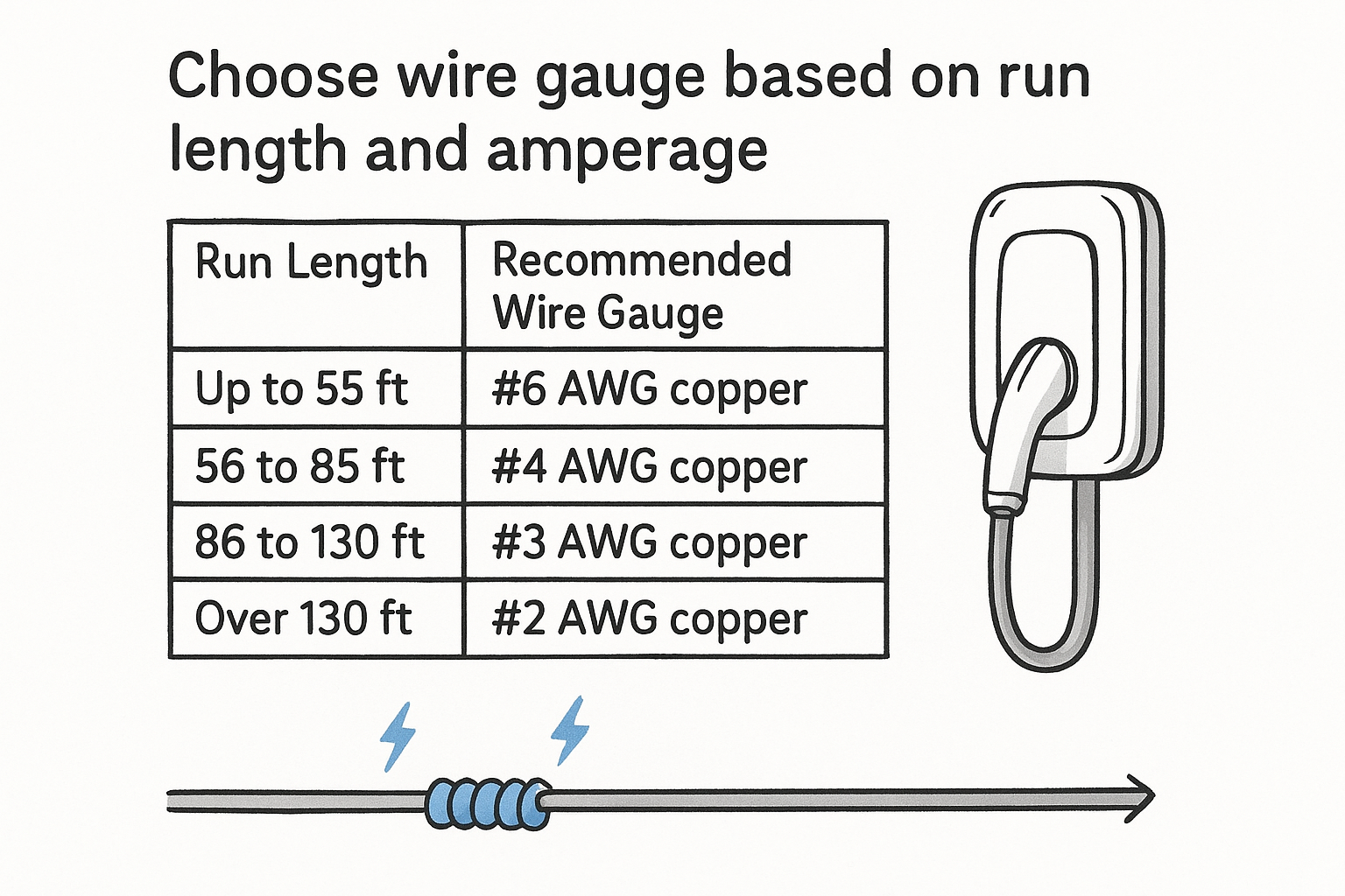
The table below shows wire gauge recommendations for a 60-amp, 240-volt circuit at the distances most homeowners encounter:
| Run Length | Recommended Wire Gauge | Notes |
|---|---|---|
| Up to 55 ft | #6 AWG copper | Standard for most attached garages |
| 56 to 85 ft | #4 AWG copper | Larger wire offsets voltage drop |
| 86 to 130 ft | #3 AWG copper | Required for longer runs to detached structures |
| Over 130 ft | #2 AWG copper | Consult an electrician for a full load calculation |
Always measure the full wire path, not the straight-line distance. Routing wire through walls, up to a ceiling, and back down to the unit easily adds 15 to 20 feet you might not account for on paper.
Select and plan your conduit
EMT (electrical metallic tubing) conduit is the most common choice for exposed runs in garages and along exterior walls, and most Arizona jurisdictions accept it for this application. PVC Schedule 40 conduit works well for underground runs, such as crossing a driveway to reach a detached garage. Any tesla wall connector wiring diagram you reference should account for conduit fill rules, which limit how many conductors you can pull through a given conduit diameter.
For a three-conductor run (L1, L2, ground) of #6 AWG wire, 1-inch EMT conduit handles the fill requirement comfortably. Moving up to #4 AWG means you need 1.25-inch conduit to stay within the 40 percent fill limit NEC Article 358 sets for EMT. Buy your conduit fittings, connectors, and straps at the same time so you have everything on hand before you start pulling wire.
Step 4. Land wires using a clear wiring diagram
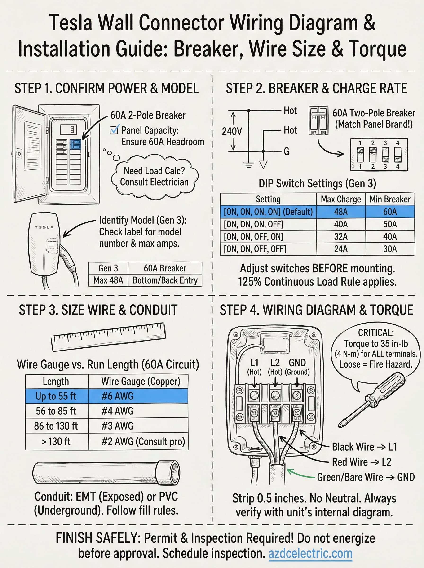
With your wire pulled through conduit and your breaker sized correctly, the terminal block is the final critical connection point in the entire installation. This is the step where a clear tesla wall connector wiring diagram pays off directly. The Gen 3 Wall Connector terminal block sits behind the removable front cover and accepts three conductors: L1 (hot), L2 (hot), and ground. There is no neutral wire in this circuit. Confirm the front cover is off and the unit is not yet energized before you touch any terminal.
Identify the terminal block connections
The terminal block on the Gen 3 Wall Connector is clearly labeled, but the physical position of each terminal from left to right can catch you off guard if you approach it without a reference. Use the diagram printed inside the unit’s cover as your primary guide, and cross-reference it with the terminal layout below before you seat any conductor.
| Terminal Label | Connection | Wire Color (Standard) |
|---|---|---|
| L1 | Hot leg 1 from breaker | Black |
| L2 | Hot leg 2 from breaker | Red |
| GND | Equipment ground | Green or bare copper |
Strip each conductor to exactly 0.5 inches before inserting it into the terminal. Too much exposed conductor creates a short risk against adjacent terminals; too little means the clamp won’t make full contact. Insert each wire straight into its corresponding terminal opening and confirm the conductor seats fully before you tighten the screw.
Reversing L1 and L2 does not damage the charger or your vehicle, since the Wall Connector uses both hot legs interchangeably for 240-volt AC power. However, leaving the ground terminal loose or unconnected is a serious safety violation that will fail inspection.
Torque each terminal to spec
Tesla specifies a torque value of 35 in-lb (4 N-m) for all three terminal screws on the Gen 3 Wall Connector. That number is not a guideline; it is the manufacturer’s requirement for a safe, lasting connection. Under-torqued terminals generate heat at the contact point as current flows through a loose connection, and that heat builds up over hundreds of charge cycles. Use a torque screwdriver set to 35 in-lb and apply it to each terminal in sequence: L1, L2, then GND.
After torquing all three terminals, give each wire a firm tug to confirm it does not pull free from the clamp. Reinstall the front cover, then notify your inspector that the unit is ready for the final review.
Finish the install safely
With your terminals torqued, your cover reinstalled, and your permit in hand, you have one task left: schedule your inspection before you energize the circuit. Contact your local building department, confirm the inspection date, and keep your tesla wall connector wiring diagram and permit paperwork accessible at the job site. An inspector will check your breaker rating, wire gauge, conduit work, and terminal connections against code, and passing that review is the only thing that confirms your installation is safe and legal.
Once the inspector signs off, flip the breaker on and confirm the Wall Connector powers up with a solid green light. Plug in your Tesla and verify the charge session starts at the expected rate based on your DIP switch setting. If anything looks off, stop and troubleshoot before driving on the charge.
Prefer to skip the permit process and have a licensed electrician handle every step? Book an EV charger installation with AZ DC Electric and we will take it from there.